top of page
Search
tomsenior

Ring Wheel & Spider

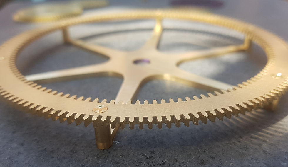
The 312 tooth epicyclic ring-wheel and spider are one of the main points of interest of Strutt's clock, and this section covers the unusual processes needed to manufacture these components.
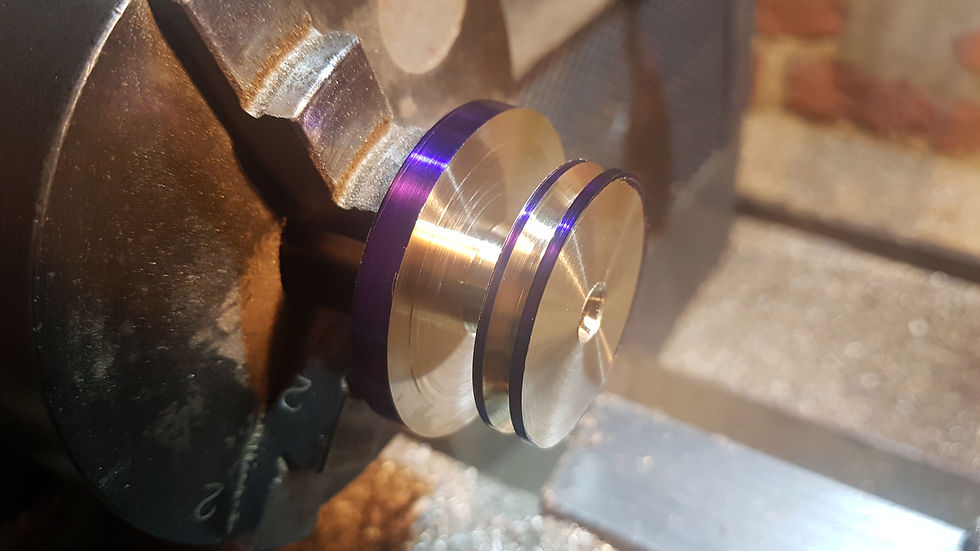
Turning the fly-cutter, which will be used for cutting the inner teeth of the ring-wheel.

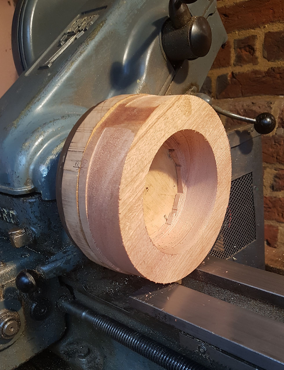
A wooden arbor turned on the 7" faceplate, which will be used to mount the ring-wheel blank.

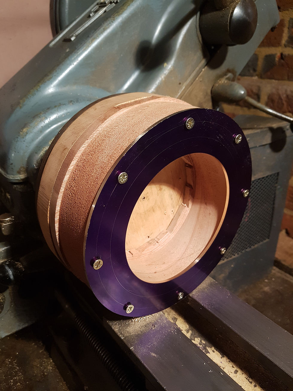
The ring-wheel blank mounted on its wooden arbor..

Performing a trepanning cut on the ring-wheel blank.

Waste stock removed and the internal ID turned to the correct dimension.

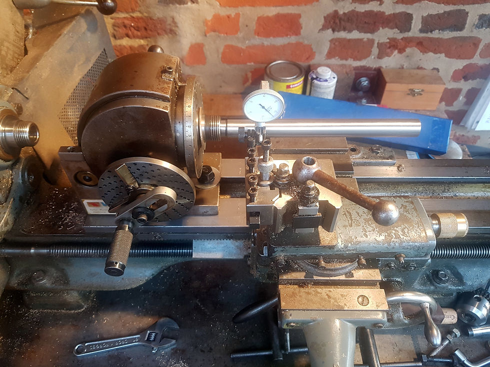
Truing the dividing head on the lathe, with the dial test indicator

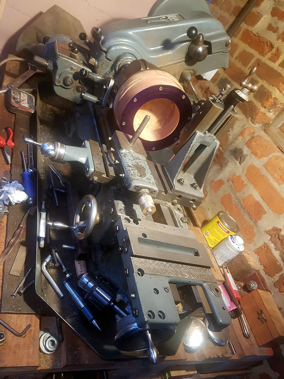
When configuring the lathe in this unusual setup, I elected to fit a spare saddle on the ways, which would be used to mount the motor for the fly cutter. This avoided needing to drill any holes into the Myford. This image shows the dual saddle arrangement, prior to fitting the motor mounting plate.

Setting up for welding the fly-cutter drive band - once the correct length had been determined. This is achieved by heating both sections with a red hot scalpel, prior to fusing them together.

The final setup for cutting the ring-wheel internal teeth. The cross slide was locked for rigidity and the vertical slide was locked once the correct depth of cut for the teeth had been determined. The saddle was linked to the secondary saddle with a rigid bar, to ensure that they moved in tandem (preventing over tension of the drive belt between the motor and the fly-cutter.) The motor sits on a mounting plate which is bolted into the secondary (temporary) saddle.

Cutting the internal teeth on the ring-wheel.

Cutting the internal teeth of the ring-wheel. In this mode, a traditional PP Thornton cutter is being used as a fly-cutter. Note the counter weight and the anti-rotation lock pin. See video below for further detail.


The completed superglue arbor, mounted to the 7" faceplate. The ring-wheel is a slip fit over the outer shoulder.

The ring wheel mounted on its superglue arbor, prior to being turned to final OD.

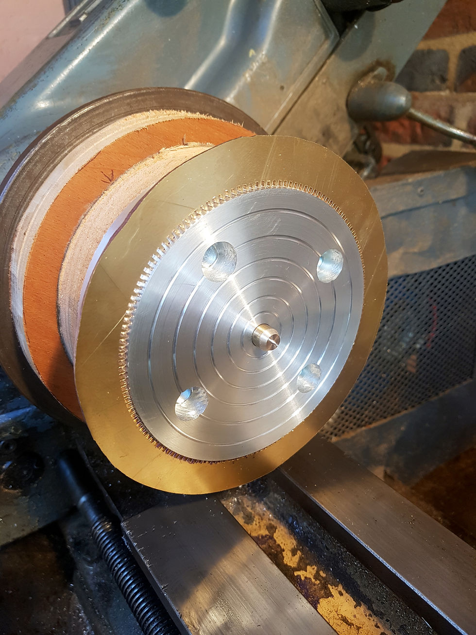
The rIng-wheel and spider blank mounted on their superglue arbor, turned to final dimensions.

I am used to using digital callipers on my projects, but due to the OD of the ring wheel being over 5", I had to resort to the traditional vernier calliper design when turning to the ring-wheel to size on the lathe.

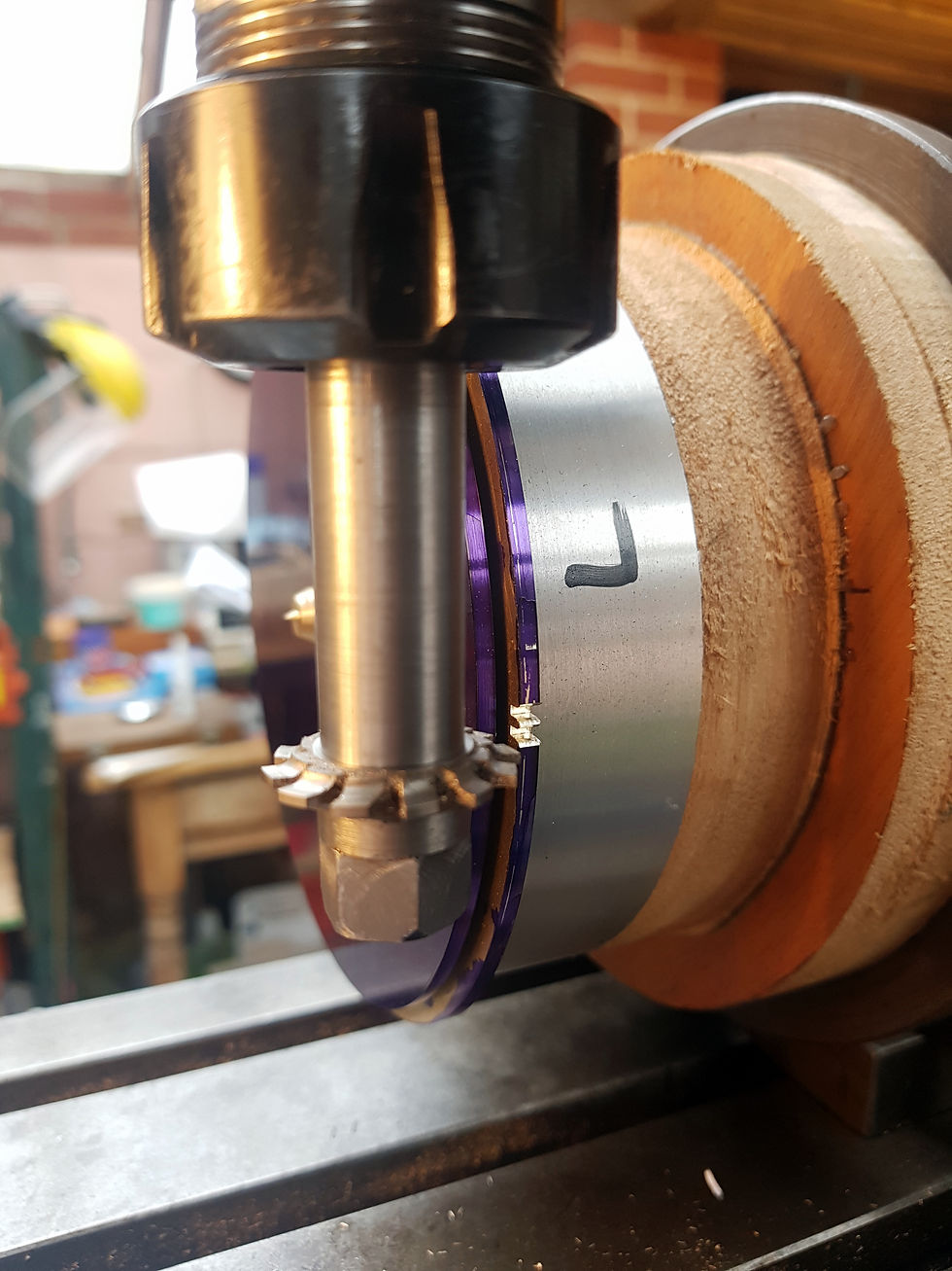
Cutting the ring-wheel outer teeth on the milling machine. In this case the PP Thornton cutter is being used in its normal configuration as opposed to being used as a fly-cutter for the internal teeth on the ring-wheel. Note that the cutter just clears the spider blank when cutting the teeth to final depth.

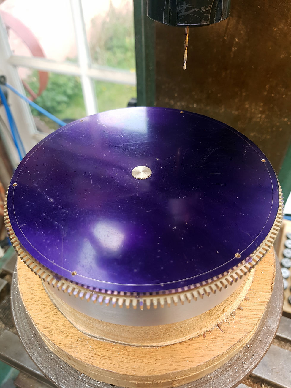
Drilling the mounting holes through the ring-wheel and spider blank. As both components are still locked onto the superglue arbor, concentricity is maintained.

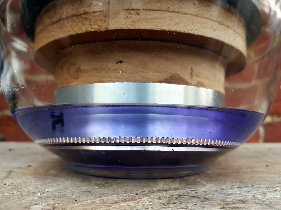
Using 95% acetone to break the superglue bond between the components and the arbor.

Ring-wheel and spider blank, removed from their arbor.

Marking out the spider legs with a divider.

Marking out completed on the spider. Note the pegs in four of the holes, used for marking out purposes with a ruler and divider.

Cutting close to the line on the fretsaw, to reduce the amount of finishing work required from my needle and escapement files.

Cutting out the spider. 5/6 completed.

Filing the spider leg down to the line. I made a custom filing guide (with alignment dowel pins), to produce a perfectly flat and straight finish. Filing is not yet completed in this image.

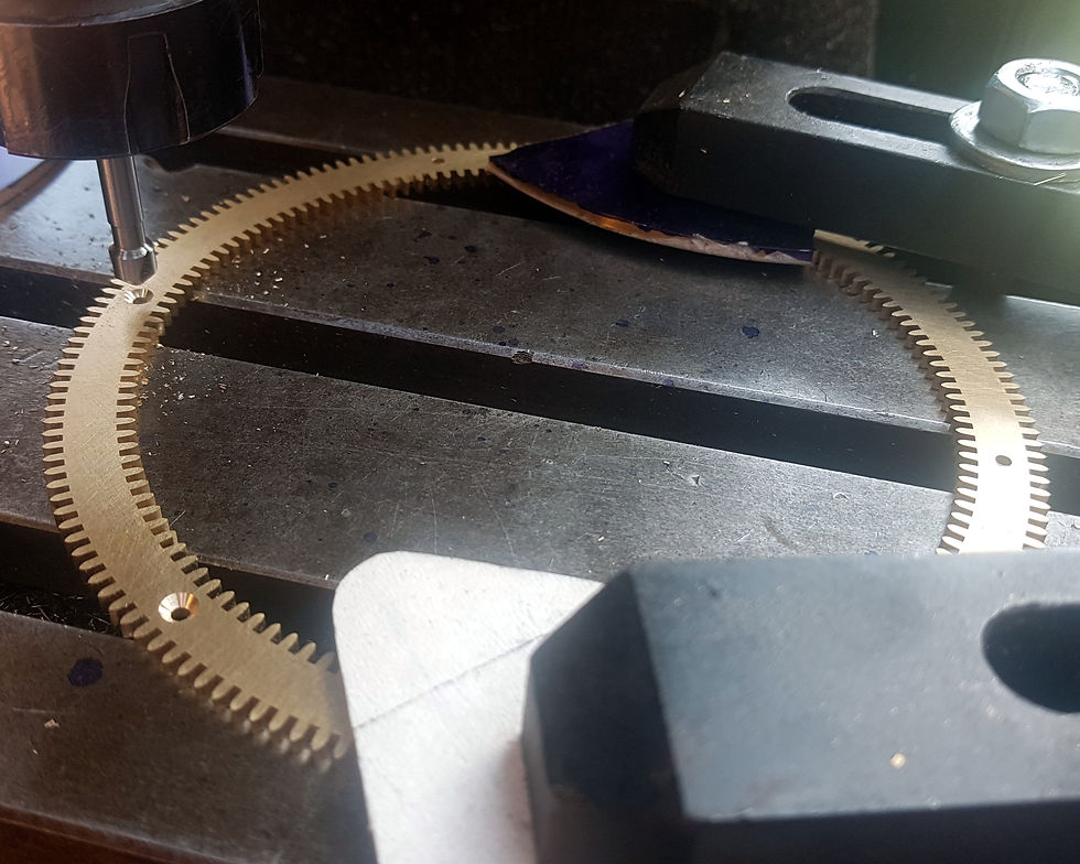
Countersinking the screw holes. Great care was taken to ensure concentricity between the original hole and the countersink.

The completed ring-wheel and spider.

The completed ring-wheel and spider. FInal sanding and polishing still to be completed.

239 views0 comments

Recent Posts

See All

The Dial

Great Wheel

Comments


bottom of page